An AI sprinkler brain that fails back to dumb
Turfy is the design for a weather-informed, camera-and-sensor irrigation controller, but the clever part isn’t the AI. It’s that it only touches the lawn when it’s provably healthy. It rides alongside a 1990s Rain Bird as a fail-safe sidecar: take authority while the watchdog is fed, and hand control straight back the instant anything goes wrong. In hardware. Because a stuck valve is a flooded yard and a very large water bill.
 The brief
Where it stands
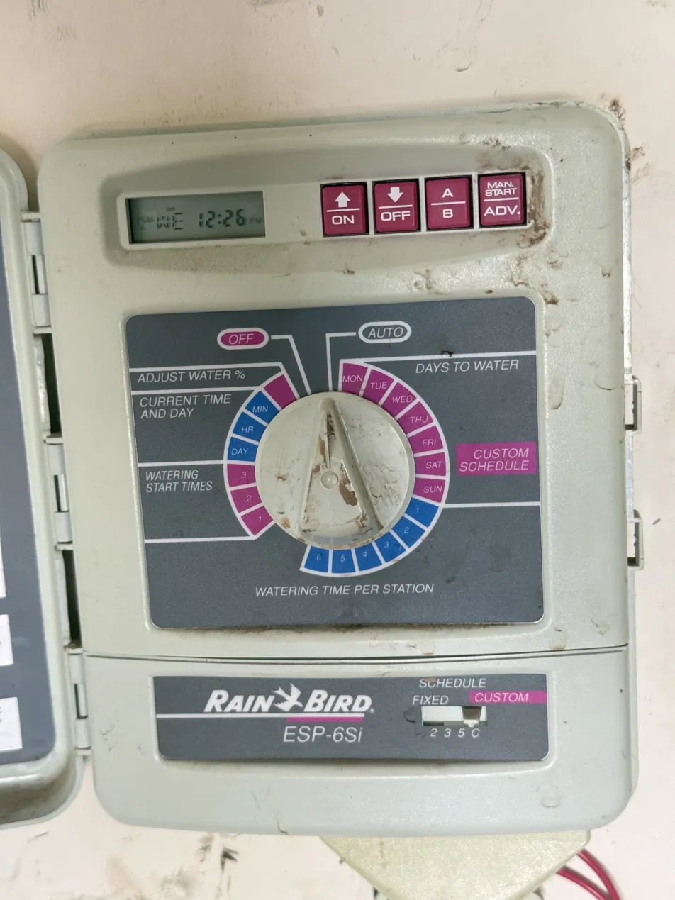
I have a simple sprinkler system at home, and I wanted an AI-driven, weather-informed one without ever making the yard depend on a Raspberry Pi. This page is the design for that. The controller has been opened and mapped, and the first build package is drawn. The board has not been built, and nothing here has ever switched a valve.
| Piece | What it is | State |
|---|---|---|
| The Rain Bird, opened and mapped | Five photographs, three boards, the tap point found. | done |
| v0.1 build package | Four schematic sheets, channel map, pin map, parts list, acceptance test. | drawn |
| The sidecar board | Two relay boards, the watchdog, the sense bank. | not built |
| The turfy daemon | Heartbeat, zone driver, scheduler. | not written |
| Acceptance test | Five steps, before a valve is connected. | not run |
| Phases 0 to 3 | Passive logging through weather and vision. | not started |
docs/turfy, the v0.1 build package and the teardown notes, 9 July 2026. No hardware exists to measure.
Safe by construction
Rain Bird keeps authority
The 1990s controller stays wired exactly as it is. Turfy is a sidecar on the station outputs. It never replaces the brain; it borrows it.
A hardware dead-man
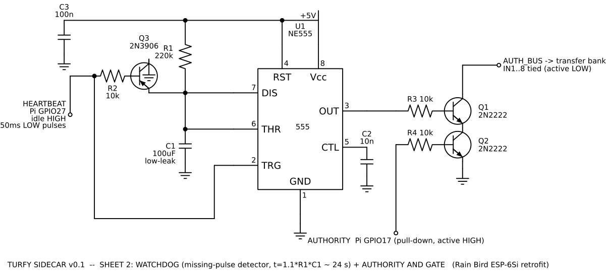
A 555 missing-pulse watchdog must be fed by the daemon’s own main loop, one pulse every 10 seconds or less. Go quiet for about 24 seconds and the transfer relays physically drop.
Fail back to dumb
Power loss, kernel panic, a crashed or hung daemon: each one reverts to the Rain Bird with zero software involved. A stuck valve floods a yard, so this can’t stick.
The invariant the whole design hangs on
A de-energized transfer bank leaves the Rain Bird wired exactly as it is today. It’s the first line of the acceptance test, proven with a continuity meter before anything is ever powered on. Pull Turfy’s power in the middle of a watering cycle and the system is stock.
The transfer-switch architecture
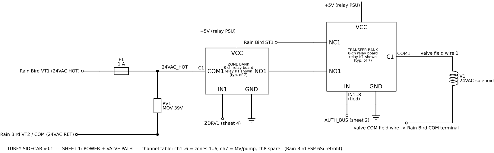
It’s the classic automatic-transfer-switch pattern applied to sprinklers. An SPDT relay per zone: Rain Bird output on NC, Turfy output on NO, valve wire on the common pole. One authority line pulls the whole bank. Unpowered, crashed, or watchdog-tripped, the relays drop and the Rain Bird is back in control.
The valve common stays on the Rain Bird’s COM terminal and is never moved or switched. Turfy’s valve supply is tapped from the Rain Bird’s own 24VAC terminals, behind a 1 A fuse and a 39 V MOV. With one transformer, paralleled outputs are harmless even during relay bounce.
The one rule that must survive every revision: never run a second 24VAC transformer while the NC path to the Rain Bird exists. Out-of-phase secondaries through the transfer relay = circulating current and dead triacs. Turfy steals 24VAC from the Rain Bird’s own terminals so both controllers switch the same hot leg.
The safety core
“The heartbeat must prove application liveness, not kernel liveness.”
So it’s toggled from the daemon’s own main loop, not a background timer. A timer would keep ticking after a crash and defeat the entire point. Never a cron job, never hardware PWM.
Authority = liveness ∧ intent
Two 2N2222s in series pull the transfer bank low. It engages only when the 555 says the daemon is alive and the Pi explicitly asserts yes. Either transistor off → the line floats high → the bank drops → Rain Bird.
authority ⇔ (heartbeat alive) ∧ (Pi says yes)
The watchdog, in numbers
- Circuit
- NE555 missing-pulse detector
- R1
- 220 kΩ
- C1
- 100 µF, low leakage
- Timeout, 1.1 × R × C
- about 24 s
- Heartbeat, GPIO27
- 50 ms low pulse, every 10 s or less
- Authority, GPIO17
- pull-down default, active high
- Authority gate, Q1 and Q2
- two 2N2222 in series
Sheet 2 and the pin map, build package v0.1. Nominal part values.
Boot sequence: safe at every step
- 1Pi boots. AUTHORITY GPIO defaults pull-down → Rain Bird stays in control regardless of any GPIO chatter.
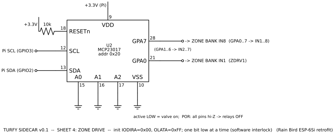
- 2MCP23017 powers up all-inputs (POR default) → zone relays held off. Defined state, no init race.
- 3turfy.service self-checks (I²C ack, config sane, time synced), starts the heartbeat, then raises AUTHORITY.
- 4Watchdog charges within one timeout; the transfer bank engages and Turfy is driving.
Every way it can fail
Seven failure modes. Four end at the Rain Bird with no software in the path. One is harmless by construction. One depends on the daemon noticing. And one the watchdog cannot see at all, which the build package says in so many words.
The bench is the design run as a state machine: the logic on the four sheets, not telemetry. Boot it, then break it.
Valves answer toRain Bird
- turfy daemon
- Pi unpowered
- HEARTBEAT, GPIO27
- silent
- C1, the watchdog’s capacitor
- 0.00 V, trips at 3.33 V
- 555 OUT, into Q1
- LOW: Q1 open
- AUTHORITY, GPIO17, into Q2
- LOW on its pull-down: Q2 open
- Relay boards, 5 V
- off
- Authority bus
- floats HIGH
- Transfer bank
- DROPPED, valve wires on NC
- restTurfy is unpowered. Every transfer relay rests on NC: the Rain Bird is wired exactly as it was.
Model, computed in your browser from the v0.1 build package: sheet 2 and the failure table. Its clock runs at 4× so the 24 s timeout plays in 6. No hardware is attached, because none is built.
| Failure | Result | Closed by |
|---|---|---|
| Pi power loss / kernel panic | Heartbeat stops → watchdog drops → Rain Bird. | the watchdog |
| Daemon crash or hang | Same: the heartbeat is owned by the daemon loop. | the watchdog |
| Pi reboot GPIO chatter | AUTHORITY pull-down + MCP23017 power-on reset = no valve action. | boot defaults |
| Relay 5 V supply dies | Transfer coils drop → Rain Bird. | the relay coil |
| Both controllers fire one zone | Harmless: shared transformer, same phase. | one transformer |
| I²C bus wedge | Zones frozen. The daemon detects the NAK → drops AUTHORITY. | the daemon |
| Healthy daemon, latched zone | Not caught by the watchdog → hard-capped by a per-zone max-runtime in the driver layer, plus a flow-meter alarm in v0.2. | software invariant |
The one hole, a latched zone with a healthy daemon, is a software invariant: hard-cap every zone activation at a maximum runtime in the driver layer itself, not the scheduler. The same layer holds a second interlock: never more than one zone at a time, for the transformer’s VA budget and for water pressure.
The four build sheets
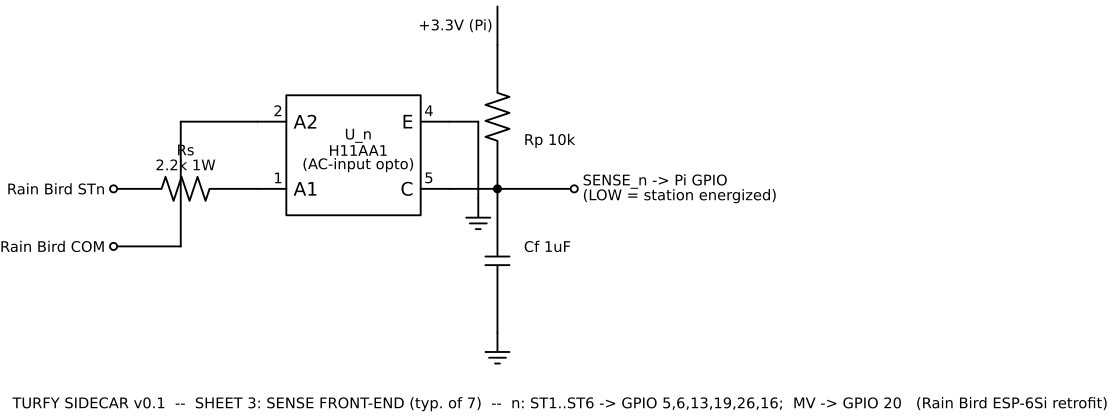
Four sheets carry the build from the 24VAC tap all the way to the Pi’s I²C bus: the valve path, the watchdog and authority gate, the sense front-end, and the zone drive. They are drawn from a parametric source, so when a board photograph changes a fact it is a one-line edit and a re-render rather than a redraw.
Reverse-engineering the box
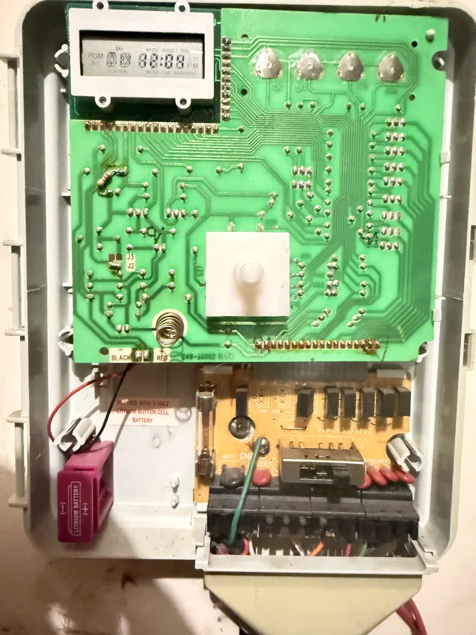
Before you can sidecar a sealed 1990s controller, you have to map it. Board by board: what’s the tap point, where does 24VAC come from, and is the fallback actually trustworthy?
 Fully mapped
What the photographs settled
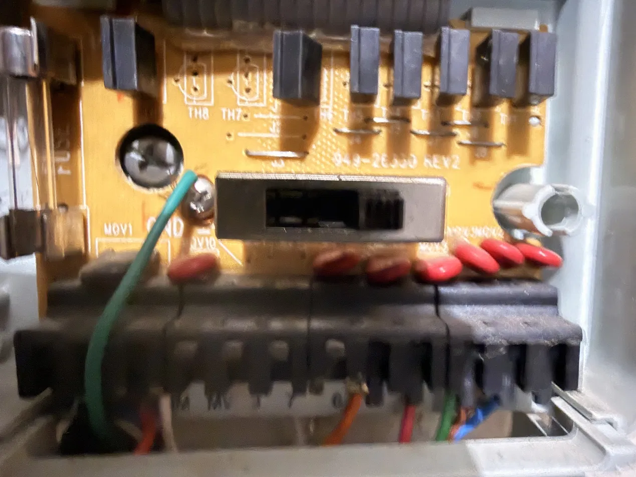
The tap point. Field wires land on a screw terminal block on the power board, so the sidecar never touches these boards. The Rain Bird already fuses and clamps its own side; Turfy’s fuse and MOV protect the tap independently. The green wire is earth to the chassis: it stays, and Turfy’s logic ground stays unbonded from it.
What they could not
- The terminal block legend. Whether the master-valve terminal is broken out on the 6Si is not readable here. The eighth triac position suggests the board supports it.
- The transformer’s VA rating, which sets how many coils the shared supply tolerates during a handover.
- The battery. It holds the time and the program through an outage, so it is worth metering: if it is dead, the fallback boots into a default program.
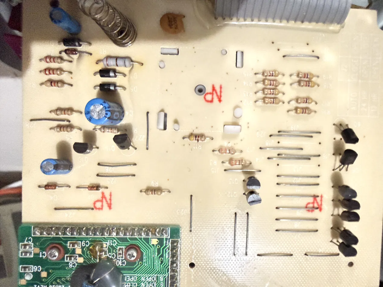
- Triac leakage. With the Rain Bird off, each triac leaks a little through its MOV network into the sense optos. With a 2.2 kΩ series resistor that should read as off. The teardown notes still want it proven, not assumed: scope a SENSE line with the station idle and see a solid high. That would be a sixth step; the acceptance test below has five.
 The tap point
 The drivers
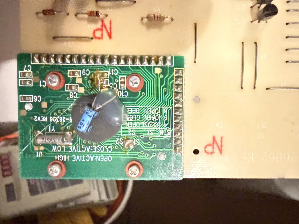 The blob
Validate each layer
None of the four phases has run. Phase 0 is first for a reason: a couple of weeks of passive logging puts the whole software stack on real signals while the old brain is still driving.
Passive learn
An H11AA1 opto per station output logs when the Rain Bird actually waters. Validates zone mapping and collects a baseline schedule at zero risk, since Turfy never asserts.
Take authority
Transfer relays + watchdog go live. Turfy replicates the dumb schedule first, proving the fail-safe handover with a meter before anything smart happens.
Flow metering
An inline pulse flow meter learns each zone’s baseline GPM. That’s the killer feature: it detects stuck valves, broken heads (flow too high) and clogged lines (flow too low), per zone.
Weather + vision
ET-based scheduling (Penman-Monteith / Hargreaves) scales runtime to replace the daily deficit, minus rainfall. A cheap camera adds an NDVI-ish turf-stress index on top.
The v0.1 build package
Two stock relay boards, an MCP23017 for a defined power-on state, a 555 watchdog, and an H11AA1 sense bank: everything a Turfy v0.1 board needs, laid out across the four sheets above.
| Part | Role |
|---|---|
| 2× 8-channel 5 V opto relay board, SPDT, NO and NC exposed | transfer bank, zone bank |
| 1× MCP23017 | zone drive, defined power-on state |
| 1× NE555 + 2N3906 + 220 kΩ + 100 µF + decoupling | watchdog |
| 2× 2N2222 + 10 kΩ | authority AND |
| 7× H11AA1 + 2.2 kΩ 1 W + 10 kΩ + 1 µF | sense bank |
| 1× 1 A fuse and holder, 39 V MOV | 24VAC tap protection |
| 1× 5 V 2 A supply | relay coils |
| 1× Raspberry Pi, on its own 5 V supply | the daemon |
| Signal | Notes |
|---|---|
| AUTHORITYGPIO 17 | out. Pull-down default; high requests control. |
| HEARTBEATGPIO 27 | out. Idle high; 50 ms low pulse every 10 s or less, from the daemon main loop only. |
| I²C1GPIO 2, 3 | bus. MCP23017 at 0x20. |
| SENSE 1 to 6GPIO 5, 6, 13, 19, 26, 16 | in. H11AA1 outputs; low means a Rain Bird station is energized. |
| SENSE MVGPIO 20 | in. Same, for the master valve. |
| spareGPIO 21 | in. Reserved for flow-meter pulses. |
Acceptance test, before a valve is connected
- 1Transfer bank unpowered: continuity from every Rain Bird station terminal to its valve terminal, all 8 channels. The Rain Bird path is intact.
- 2Power logic only, no 24VAC: boot the Pi and verify every relay stays silent through two full reboots. The GPIO chatter test.
- 3Start the daemon; confirm the transfer bank engages only after AUTHORITY is high and the heartbeat is running. Kill -9 the daemon: the bank must drop within about 24 s.
- 4Pull the heartbeat wire with the daemon running: same result.
- 5Apply 24VAC with a dummy load on channel 1, a 24 V lamp or a spare solenoid: a Rain Bird manual start drives it with authority off, and MCP23017 bit 0 drives it with authority on.
The rest of the hand-built pages are on the projects index.